|

 OPERATION OPERATION
The KSF-200 Fuse Unit (for SPM-20T and
SPM-20B Power Fuses)
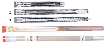
The KSF-200 Fuse Unit consists of a fusible element, an arcing rod,
and a solid-material arc-extinguishing medium contained within a
filament-wound glass-epoxy tube.
The fusible element is connected at one end--through a
current-transfer bridge-to the fuse-unit exhaust ferrule. At the
other end, the fusible element is connected to the arcing rod which
extends upward through the stepped bore in the fuse unit. A drive
spring located inside the fuse unit provides the stored energy to
drive the arcing rod upward through the arc-extinguishing medium
during fault-current interruption. At the same time, the drive
spring forces the actuating pin upward to trip a blown-fuse target
in the fuse-unit upper end fitting
Over current melts the silver fusible element.
then transfers to the strain wire, which volatilizes instantly.
Arcing is initiated as illustrated.
Released force of the drive spring thrusts the
arcing rod upward. causing rapid elongation of the arc in the
solid-material-lined bore of the fuse unit. Under maximum fault
conditions. heat from the confined arc causes the solid material in
the large-diameter section of the arc-extinguishing chamber to
undergo a thermal reaction-generating turbulent gases and
effectively enlarging the bore diameter so that the arc energy is
released with a mild exhaust Under low-to-moderate-fault
conditions, the arc is extinguished in the upper section of the
arc-extinguishing chamber-where the small-diameter bore effectively
concentrates the deionizing gases for rapid arc extinction.
Continued upward travel of the arcing rod
after rod arc extinction causes the actuating pin to penetrate the
upper seal resulting in the projection of a brilliant-red blown-fuse
target from the fuse-unit upper end fitting.
 STYLES AND
CONSTRUCTION STYLES AND
CONSTRUCTION
¡¡
 |
<SPM20T and SPM-20B Power Fuses>
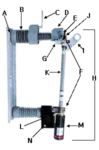
SPM-20T Power Fuse (45¢ª Opening) |
A Rugged 3/16 - Inch thick flanged, formed-steel base
features three-point mounting to simplify installation, and to
minimize possibility of deforming base when bolting to an irregular
surface
B Shin Shin Cypoxy Insulators.. employing shin shin
cycloaliphatic epoxy resin system. Cypoxy is self-scouring, non
tracking. non weathering.. there's never a compromise of insulation
integrity
C Load Interrupter provides 200-ampere single-pole live
switching of single-phase and three-phase circuits
E Fault-closing contacts provide a one-time duty -cycle fault
closing capability equal to the interrupting rating of the fuse
(Expressed in amperes rms asymmetrical), and a two-time duty cycle
fault-closing capability of 13,000 amperes rms asymmetrical;
fault-closing contacts also provide self-guiding action for fuse
unit (or holder) during opening or closing
F Spring-backed upper and lower mounting contacts are copper,
heavily silver clad, and are bifurcated to provide four-point
contact at each end of the fuse-unit assembly or holder
G Pull-ring-operated latch provides positive, secure
engagement of fuse-unit assembly or holder
H KSF-200 Fuse Unit Assembly-removable assembly inculding
I Upper end fitting with large, accessible and easily
operated pull ring
J Brilliant-red blown-fuse target....projects from the upper
end fitting when the fuse operates. Fuse condition is easily checked
with fuse in the closed position, Target resets when blown fuse unit
is replaced
K KSF-200 Fuse Unit-expendable after fault-clearing operation
L Aluminum-bronze lower end fitting-securely engages
stainless-steel hinge pivot rod smooth opening and closing operation
M Silencer-Shin Shin exhaust control device that
virtually-eliminates venting, Fuse operation is silent
N Zinc-plated Hot-rolled steel hinge provides positive,
self-guiding action for the fuse unit (or holder) during opening and
closing. Current is transferred directly from lower contacts to a
separate, tin-plated copper two-hole terminal pad
AVAILABLE MOUNTING STYLES AND RATINGS
¡¡
|
Style |
Fuse Type |
Rating |
|
Kv |
Amperes, Rms |
| Nom |
Max Des |
BIL |
Max |
Live
Switching |
Interrupting (Sym) |
Disconnect
45¢ª Opening Silencer Vertical |
SPM-20T |
23 |
25.8 |
125 |
200K or 200E |
200 |
12500 |
| SPM-20B |
13.8 |
17.0 |
95 |
200E |
200 |
12500 |
 FUSE HANDLING FUSE HANDLING
Fuse Handling-Type SPM-20T SPM-20B Power Fuses with Load
Interrupter
Shin Shin Type SPM-20T and SPM-20B Power Fuses are best handled
using Grappler-Shin Shin fuse-handling fitting that features
cushion-grip coated prongs for the sure grip and ready control that
operators appreciate when removing or installing a fuse unit,
holder, or switch blade. And for live-switching operations, a hook
stick equipped with Grappler (as described below) is all that is
required to initiate circuit interruption within
Switching with Load Interrupter
Load interrupter offers the ultimate in live-switching simplicity :
just a firm, steady opening pull on the fuse with a hook stick
equipped with Grappler provides quick-break direct-drive action of
load interrupter internal moving contact through the
arc-extinguishing chamber, Circuit interruption is accomplished by
the deionizing gases generated by thermal reaction of the arc on
Shin Shin uniquely formulated chamber liner and moving-contact
trailer - there is no external arc or flame
At the end of the moving-contact opening stroke, after the arc has
been extinguished, the external current-carrying contacts part. Then
Load Interrupter automatically self-resets for the next opening
operation. Switching is easily accomplished without the strained
twist-and-pull effort often associated with elbows... without
complex gas-assisted or force-multiplying gadgets. The required
operating force does not
increase with time. And there are no unwieldy cables to wrestle
or components to park.
Circuit closing is easy, too. A swift nonhesitating stroke with a
hookstick is all that's required. Load Interrupter fault closing
contacts and the fuse hinge provide an express, self-guiding action
for the fuse – there are no hard-to-see components that must be
jockeyed into critical alignment before closing.
Circuit-closing inrush currents(including fault currents) are picked
up by the fault-closing contracts of the Load Interrupter and the
fuse¡¦.not by current-carrying contacts, nor by interrupting
contacts. This allows fault closing without contact destruction,
preserving the operating integrity of Load Interrupter.
Application Notes
Shin Shin SPM Power Fuses with Load Interrupter are suitable for
the following single-pole live-switching duties in single-phase or
three-phase circuits of distribution systems rated 23kv.
Live Switching – Opening
Transformer switching – transformer load currents up through 200
amperes, as well as transformer magnetizing currents associated with
the applicable loads.
Line switching – load splitting(parallel or loop switching) and load
dropping(charging currents typical for distribution systems of these
voltage ratings).
Cable switching – load splitting(parallel or loop switching) and
load dropping of currents up through 200 amperes ; also cable
dropping(charging currents typical for distribution systems of these
voltage ratings).
Live Switching – Closing
Circuit closing – inrush currents associated with the above opening
duties.
Duty-cycle fault closing – for Shin Shin Type SMP Power Fuses, a
one-time fault-closing capability equal to the interrupting rating
of the fuse(in amperes rms asymmetrical : 22,400 for the SPM-20 at
14.4kv;20,000 at 23kv), and a two-time fault-closing capability of
13,000 amperes rms asymmetrical at 14.4kv or 23kv. These values
represents the fault-closing capabilities of the fuse with Load
Interrupter when the fuse is closed with a purposeful thrust without
hesitation. Following the specified number of such closings(one or
two), will remain operable and able to carry and interrupt rated
current.
INTERRUPTING RATINGS
Short-Circuit Interrupting Ratings
The maximum interrupting ratings of fuses listed based upon full
line-to-line voltage across a single fuse. Obviously this is only
one criterion of fuse performance. These fuses have also been
rigorously tested through the full spectrum of fault currents, from
the lowest to the highest fault – not only primary faults but also
secondary-side faults as seen from the primary side of the
transformer – and under all realistic conditions of circuitry. In
all Shin Shin testing, especial attention is given to establishing
and controlling circuit parameters to duplicate conditions as severe
as those which will be encountered in the field. This involves
testing at all degrees of asymmetry and matching of the rate of rise
of transient recovery voltage of the test circuit to that found in
actual field applications. This rate of rise depends, in turn, on
carefully established laboratory test conditions to obtain realistic
natural frequencies and typical amplitudes of transient recovery
voltage.
The short-circuit interrupting ratings listed in columns 3, 4 and 7
of these tables have been determined in accordance with the
procedures described in ANSI Standard C37.41-2000. Moreover, with
respect to the requirement in this standard for testing with
circuits having an X/R ratio of at least 15(corresponding to an
asymmetry factor of 1.55), S&C¡¯s tests were performed under the more
severe condition of X/R=20, corresponding to an asymmetry factor og
1.6. Based upon the recognition that there are many applications
where the X/R ratio is less severe than the value of 15 specified by
the standard, higher symmetrical interrupting ratings are listed in
columns 5 and 6 for X/R = 10 and 5, respectively.
SPM-20T AND SPM-20B POWER FUSE-60Herz
Short-Circuit Interrupting Ratings
¡¡
|
Kv, Norminal |
Amperes, Rms, Interrupting |
Mva, Interrupting, Three-Phase
Symmetrical, Based on X/R=15 |
|
SPM-20T&SPM-20B(with ksf 200 Fuse Unit) |
System |
Asymmetrical |
Symmetrical |
|
Based on X/R=15 |
Based on X/R=10 |
Based on X/R=5 |
|
23 |
14.4
23.0 |
20 000 |
12 500 |
13 800 |
16 000 |
500 |
SPM-20T and SPM-20B Power Fuses are available in ratings of 13.8 kv
and 23kv, only.
¡¡ |


